Ordinate dimensions measure and represent the x-axis or y-axis distance from the specified origin to the defining point in primary and alternate units. To define the placement, the ordinate dimension entity requires the origin point from which the dimension will start, the definition point on which the dimension will end, leader end point to which the extension line is drawn, text point that defines the location of the dimension text box, and the normal which orients a dimension in WCS.
An ordinate dimension entity can be rotated, scaled, and oriented in WCS.
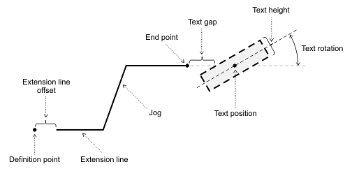
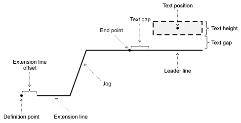
Elements of an ordinate dimension
An ordinate dimension entity consists of the following elements (no dimension lines):
- Extension line— Two lines perpendicular to the definition axis (x- or y-axis) connected by the jog; first line is from the definition point to jog line, and the second line is from the jog line to the end point. The extension line can be offset from the definition point. The extension line has color and lineweight independent of the entity's properties. The extension line can have a fixed or free length.
- Dimension text box — A linear structure that consists of the required primary text box, optional alternate measured value, optional primary and alternate tolerance value, optional primary and alternate prefix, and optional primary and alternate suffix. The dimension text box can be centered on or placed above the extension line, offset from the extension line, rotated, or scaled.
- Optional leader line — When the Dimtad property is set to 1 (the dimension text box is placed above the extension line) or to 4 (the dimension text is placed under the dimension line), the leader line is drawn from the end point to the dimension text box. The text gap specifies both the distance from the leader line to the dimension text box and from the end point along the leader line.
For working with ordinate dimension objects, use the OdDbOrdinateDimension class, which represents an ordinate dimension entity and manipulates its properties. The OdDbOrdinateDimensionPtr class is the typified smart pointer to an instance of this entity and is used for storing and passing a reference to the ordinate dimension object.
To create and initialize a new instance of an ordinate dimension entity, see Overview of Specific Entities.
The main methods of the OdDbOrdinateDimension class are listed below:
- origin() — Returns the origin and primary definition point as an object of the OdGePoint3d class.
- setOrigin() — Sets a new origin and primary definition point; requires an object of the OdGePoint3d class as a new point.
- definingPoint() — Returns the defining point as an object of the OdGePoint3d class.
- setDefiningPoint() — Sets a new defining point; requires an object of the OdGePoint3d class as a new point.
- leaderEndPoint() — Returns the leader end point as an object of the OdGePoint3d class.
- setLeaderEndPoint() — Sets a new leader end point; requires an object of the OdGePoint3d class as a new point.
- useXAxis() — Sets this dimension entity to measure the OCS X-axis distance between the origin and the defining point.
- useYAxis() — Sets this dimension entity to measure the OCS Y-axis distance between the origin and the defining point.
- isUsingXAxis() — Returns true if this dimension entity measures the OCS X-axis distance between the origin and the defining point
- isUsingYAxis() — Returns true if this dimension entity measures the OCS Y-axis distance between the origin and the defining point
The next example demonstrates how to work with an ordinate dimension entity.
// Create the line to be dimensioned
OdDbLinePtr pLine = OdDbLine::createObject();
pLine->setDatabaseDefaults(pDb);
bBTR->appendOdDbEntity(pLine);

// Set line start and end points - origin and definition points for dimension
OdGePoint3d startPoint(0.0, -5.0, 0);
OdGePoint3d endPoint(2.0, -1.0, 0);
pLine->setStartPoint(startPoint);
pLine->setEndPoint(endPoint);

//Create the base ordinate dimension
OdDbOrdinateDimensionPtr pDimensionBase = OdDbOrdinateDimension::createObject();
// Set dimension defaults
bBTR->appendOdDbEntity(pDimensionBase);
pDimensionBase->setDatabaseDefaults(pDb);

//Set dimension parameters
OdGePoint3d leaderEndPoint;
leaderEndPoint = startPoint + OdGeVector3d(1.0, 0, 0.0);
pDimensionBase->setOriginstartPoint);
pDimensionBase->setDefiningPoint(startPoint);
pDimensionBase->setLeaderEndPoint(leaderEndPoint);
// Measure distance by Y-Axis
pDimensionBase->useYAxis();

//Create an ordinate dimension
OdDbOrdinateDimensionPtr pDimension = OdDbOrdinateDimension::createObject();
// Set dimension defaults
bBTR->appendOdDbEntity(pDimension);
pDimension->setDatabaseDefaults(pDb);
//Set dimension parameters
leaderEndPoint = endPoint + OdGeVector3d(3.0, 1.0, 0.0);
pDimension->setOrigin(startPoint);
pDimension->setDefiningPoint(endPoint);
pDimension->setLeaderEndPoint(leaderEndPoint);
// Measure distance by Y-Axis
pDimension->useYAxis();
See Also
Overview of Angular Dimensions
Overview of Arc-Length Dimensions
Overview of Diametric Dimensions
Overview of Radial Large Dimensions
Copyright © 2002 – 2020. Open Design Alliance. All rights reserved.
|