 Description
 Description
An IfcColumn is a vertical structural member which often is aligned with a structural grid intersection. It represents a vertical, or nearly vertical, structural member that transmits, through compression, the weight of the structure above to other structural elements below. It represents such a member from an architectural point of view. It is not required to be load bearing.
There are two main representations for column occurrences:
- IfcColumn with IfcMaterialProfileSetUsage is used for all occurrences of columns, that have a profile defined that is swept along a directrix. The profile might change uniformly by a taper definition along the directrix. The profile parameter and its cardinal point of insertion can be fully described by the IfcMaterialProfileSetUsage. These columns are always represented geometrically by an 'Axis' and a 'SweptSolid' or 'AdvancedSweptSolid' shape representation (or by a 'Clipping' geometry based on the swept solid), if a 3D geometric representation is assigned.
- IfcColumn is used for all other occurrences of columns, particularly for columns with changing profile sizes along the extrusion, or columns defined by non-linear extrusion, or columns having only 'Brep', or 'SurfaceModel' geometry, if a more parametric representation is not intended.
The axis representation can be used to represent the fundamental orientation and extents of a column's body. If an IfcMaterialProfileSetUsage is used, the axis representation is used to locate the profile. In addition:
- For a body representation using an IfcExtrudedAreaSolid, the axis can be an IfcPolyline having two Points, or IfcTrimmedCurve with BasisCurve of type IfcLine. The axis curve lies on the z axis of the object coordinate system.
- For a body representation using an IfcRevolvedAreaSolid, the axis can be an IfcTrimmedCurve with BasisCurve of type IfcCircle. The axis curve lies on the x/z plane of the object coordinate system, the tangent at the start is along the positive z-axis.

As shown on the image below, the axis representation must be positioned at the IfcMaterialProfileSetUsage.CardinalPoint, and parallel to the IfcExtrudedAreaSolid.ExtrudedDirection. This offset between the axis line and the IfcExtrudedAreaSolid.Position must correlate with the chosen IfcMaterialProfileSetUsage.CardinalPoint.

The following additional constraints apply to the 'AdvancedSweptSolid' representation type:
- Solid: IfcSurfaceCurveSweptAreaSolid, IfcFixedReferenceSweptAreaSolid, IfcExtrudedAreaSolidTapered, IfcRevolvedAreaSolidTapered is supported
- Profile: see 'SweptSolid' geometric representation
- Extrusion: not applicable
- IfcExtrudedAreaSolid, IfcRevolvedAreaSolid is supported
- All subtypes of IfcProfileDef (with exception of IfcArbitraryOpenProfileDef) is supported
- All extrusion directions is supported
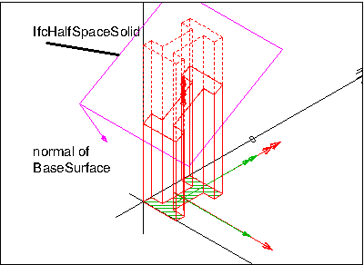
- The IfcBooleanClippingResult is supported, allowing Boolean differences between the swept solid (here IfcExtrudedAreaSolid) and one or several IfcHalfSpaceSolid
The image below illustrates a 'Clipping' geometric representation with use of IfcBooleanClippingResult between an IfcExtrudedAreaSolid and an IfcHalfSpaceSolid to create a clipped body.
- IfcExtrudedAreaSolid, IfcRevolvedAreaSolid is supported
- All subtypes of IfcProfileDef (with exception of IfcArbitraryOpenProfileDef) are supported
- All extrusion directions are supported
The image below illustrates a 'SweptSolid' geometric representation. There are no restrictions or conventions on how to use the object placement (black), extrusion placement (red) and profile placement (green).

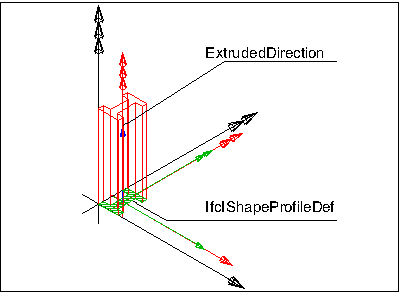
The image below illustrates use of a special profile type (here IfcIShapeProfileDef) for the definition of the IfcExtrudedAreaSolid.
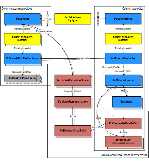
The image below illustrates assignment of IfcMaterialProfileSetUsage and IfcMaterialProfileSet to the IfcColumnType and the IfcColumn occurrence. Both the IfcMaterialProfileSet and IfcProfileDef is shared between all occurrences.

The image below illustrates cardinal point alignment. The use of IfcCardinalPointEnum must be consistent with the placement of the extrusion body provided by IfcExtrudedAreaSolid.Position.

The image below illustrates assignment of a composite profile by using IfcCompositeProfileDef for geometric representation and several IfcMaterialProfile entities within the IfcMaterialProfileSet.
This concept can be applied to the following resources:
- LoadBearing
This concept can be applied to the following resources:
- IfcColumnType
This concept can be applied to the following resources:
- IfcStructuralCurveMember - An idealized structural member corresponding to the column.
- IfcTask - A task for operating on the column.
This concept can be applied to the following resources:
- Pset_ConcreteElementGeneral
- Pset_PrecastConcreteElementFabrication
- Pset_PrecastConcreteElementGeneral
- Pset_ColumnCommon
- Pset_ReinforcementBarPitchOfColumn
This concept can be applied to the following resources:
- Qto_ColumnBaseQuantities
The IfcColumn, as any subtype of IfcBuildingElement, can participate alternatively in one of the two different containment relationships:
- the Spatial Containment (defined here)
- the Element Composition
Class Hierarchy
File: IfcColumnAutoImpl.h
Namespace: OdIfc2x3
Methods Methods
|
Returns the result of the instance resolution represented as an  RGB color object. (Inherited from OdIfcInstance) RGB color object. (Inherited from OdIfcInstance) | |

 Links
Links