 Description
 Description
An IfcMember is a structural member designed to carry loads between or beyond points of support. It is not required to be load bearing. The orientation of the member (being horizontal, vertical or sloped) is not relevant to its definition (in contrary to IfcBeam and IfcColumn). An IfcMember represents a linear structural element from an architectural or structural modeling point of view and is used if it cannot be expressed more specifically as either an IfcBeam or an IfcColumn.
There are two main representations for member occurrences:
- IfcMember with IfcMaterialProfileSetUsage is used for all occurrences of members, that have a profile defined that is swept along a directrix. The profile might be changed uniformly by a taper definition along the directrix. The profile parameter and its cardinal point of insertion can be fully described by the IfcMaterialProfileSetUsage. These members are always represented geometrically by an 'Axis' and a 'SweptSolid' or 'AdvancedSweptSolid' shape representation (or by a 'Clipping' geometry based on the swept solid), if a 3D geometric representation is assigned
- IfcMember without IfcMaterialProfileSetUsage is used for all other occurrences of members, particularly for members with changing profile sizes along the extrusion, or members defined by non-linear extrusion, or members having only 'Brep', or 'SurfaceModel' geometry, or if a more parametric representation is not intended
The axis representation can be used to represent the fundamental orientation and extents of a member's body. The image below illustrates that the axis representation can be used to represent the system length of a member that may extend past the body length of the member.

As shown on the image below, the axis representation must be positioned at the IfcMaterialProfileSetUsage.CardinalPoint, and parallel to the IfcExtrudedAreaSolid.ExtrudedDirection. This offset between the axis line and the IfcExtrudedAreaSolid.Position must correlate with the chosen IfcMaterialProfileSetUsage.CardinalPoint.
- IfcSurfaceCurveSweptAreaSolid, IfcFixedReferenceSweptAreaSolid, IfcExtrudedAreaSolidTapered, IfcRevolvedAreaSolidTapered is supported
- All subtypes of (IfcProfileDef) (with exception of IfcArbitraryOpenProfileDef) are supported
- IfcExtrudedAreaSolid, IfcRevolvedAreaSolid is supported
- All subtypes of (IfcProfileDef) (with exception of IfcArbitraryOpenProfileDef) are supported
- All extrusion directions are supported
- The IfcBooleanClippingResult is supported, allowing for Boolean differences between the swept solid (here IfcExtrudedAreaSolid) and one or several IfcHalfSpaceSolid (or its subtypes) instances
The image below illustrates a 'Clipping' geometric representation with use of IfcBooleanClippingResult between an IfcExtrudedAreaSolid and an IfcHalfSpaceSolid to create a clipped body.
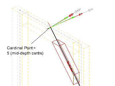
When an IfcMaterialProfileSetUsage is applied, the image below illustrates an advanced geometric representation with use of IfcBooleanClippingResult between an IfcExtrudedAreaSolid and an IfcHalfSpaceSolid to create a clipped body, with cardinal point applied as 4 (mid-depth left).

- IfcExtrudedAreaSolid, IfcRevolvedAreaSolid is supported
- All subtypes of (IfcProfileDef) (with exception of IfcArbitraryOpenProfileDef) are supported
- All extrusion directions are supported
When an (IfcMaterialProfileSetUsage) is assigned to the IfcMember:
- For all single profiles, the IfcParameterizedProfileDef.Position is NIL, or having Location = 0.,0. and RefDirection = 1.,0
- The extrusion is perpendicular to the profile direction
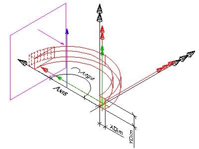
- The y-axis of the profile, as determined by IfcSweptAreaSolid.Position.P[2] points to the Z-Axis. It indicates the "role" of the column, a role=0° means y-axis of profile = Z-axis of reference coordinate system. In the exception of a vertical member, the y-axis points to the Y-axis
The image below illustrates a 'SweptSolid' geometric representation with cardinal point applied as 1 (bottom left).

If parametric profiles are used, the parameters can be interpreted to be the dimensions of the beam:
- IfcRectangleProfileDef.YDim interpreted as member width
- IfcRectangleProfileDef.XDim interpreted as member depth
- IfcCircleProfileDef.Radius interpreted as member radius
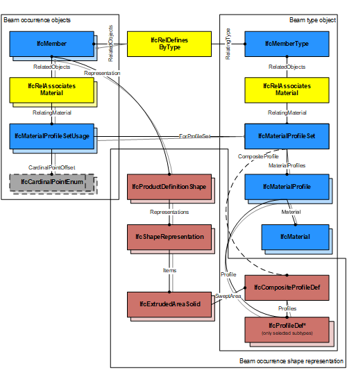
The image below illustrates assignment of IfcMaterialProfileSetUsage and IfcMaterialProfileSet to the IfcMemberType and the IfcMember occurrence. Both the IfcMaterialProfileSet and IfcProfileDef is shared between all occurrences.

Te image below illustrates assignment of a composite profile by using IfcCompositeProfileDef for geometric representation and several IfcMaterialProfile entities within the IfcMaterialProfileSet.
This concept can be applied to the following resources:
- LoadBearing
This concept can be applied to the following resources:
- IfcMemberType
This concept can be applied to the following resources:
- IfcStructuralCurveMember - An idealized structural member corresponding to the member
- IfcTask - A task for operating on the member
This concept can be applied to the following resources:
- Pset_ConcreteElementGeneral
- Pset_PrecastConcreteElementFabrication
- Pset_PrecastConcreteElementGeneral
- Pset_MemberCommon
- Pset_MemberTypeAnchoringBar (only applies to BRACE)
- Pset_MemberTypeOCSRigidSupport (only applies to MEMBER)
- Pset_MemberTypePost (only applies to POST)
- Pset_MemberTypeCatenaryStay (only applies to STAY_CABLE)
- Pset_MemberTypeTieBar (only applies to TIEBAR)
This concept can be applied to the following resources:
- Qto_MemberBaseQuantities
The IfcMember, as any subtype of IfcBuildingElement, can participate alternatively in one of the two different containment relationships:
- the Spatial Containment (defined here)
- the Element Composition
Class Hierarchy
File: IfcMemberAutoImpl.h
Namespace: OdIfc2x2_final
Methods Methods
|
Returns the result of the instance resolution represented as an  RGB color object. (Inherited from OdIfcInstance) RGB color object. (Inherited from OdIfcInstance) | |

 Links
Links