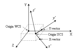
Concept of UCSs
A drawing contains two coordinate systems by default:
- World Coordinate System (WCS) — A fixed coordinate system. All geometrical objects of a drawing are defined by WCS coordinates. The WCS defines the system of absolute coordinate for all objects. For 2D views, the WCS x-axis is horizontal and the y-axis is vertical. The WCS origin is where the x-axis and y-axis intersect and define the start position for all coordinate values (0,0).
- User Coordinate System (UCS) — A movable coordinate system. Specifying coordinates for objects in the WCS is not always convenient, especially when a 3D object is built or is rendered. Therefore the real tasks require rotating and moving of the coordinate system to the point in which these tasks have more useful and suitable solutions. For that, each drawing has a user (movable) coordinate system, named UCS. Moving and rotating the UCS relative to the WCS can make work easier for individual areas of a drawing.
A UCS is an object that defines the user coordinate system that can be moved and rotated relative to the fixed world coordinate system for simplification of various tasks. A UCS is defined by the following parameters:
- Original point — Specifies the origin of the user coordinate system relative to the world coordinate system.
- X-vector — Specifies the x-direction of the user coordinate system.
- Y-vector — Specifies the y-direction of the user coordinate system.

Note: The X-vector and Y-vector must be perpendicular to construct the UCS. The z-direction is defined using the right-hand rule.