API Overview
Sometimes you may need to convert objects into a faceted mesh, for example, to get rid of complex surfaces or to export to another format.
To achieve that, you can use the oddbGetObjectMesh() method
to convert OdDb3dSolid, OdDbSurface, OdDbRegion and OdDbPolyline objects into data of that kind:
OdResult oddbGetObjectMesh(
OdDbObject *pObj,
const OdDbFaceterSettings *faceter,
OdGePoint3dArray& vertexArray,
OdInt32Array& faceArray,
OdGiFaceData*& faceData);pObj- a pointer to the object, a mesh of which you need to get;faceter- a pointer to the parameters of the partition;vertexArray- an output array of vertices;faceArray- an output array of integers describing the face definition based on the input vertex array;faceData- a pointer to the array of properties for each face.
Naturally, objects can contain faces or edges that are smooth or large in size.
To control how such objects should be converted, there is a faceter parameter, which consists of the following variables:
typedef struct MeshFaceterSettings OdDbFaceterSettings;
struct MeshFaceterSettings
{
  /** Maximal surface deviation. */
  double faceterDevSurface;
  /** Maximal normal deviation. */
  double faceterDevNormal;
  /** Grid ratio. */
  double faceterGridRatio;
  /** Maximal edge length. */
  double faceterMaxEdgeLength;
  /** Maximal aspect ratio for the grid quads. */
  OdUInt16 faceterMaxGrid;
  /** Minimal number of U parameter grid lines. */
  OdUInt16 faceterMinUGrid;
  /** Minimal number of V parameter grid lines. */
  OdUInt16 faceterMinVGrid;
  /** Faceter mesh type.
    * 0 - for quad type,
    * 1 - hybrid (triangle & quad) type,
    * 2 - triangle type.
   */
  OdInt16 faceterMeshType;
};
For illustrations of how each parameter affects the result, see the section Examples of the results in SpaModeler and ModelerGeometry Depending on Parameter Values below.
If you pass NULL instead of a pointer to the parameters, the current settings of the loaded modeler is used.
However, this may lead to unexpected results. If rendering was done before the method call, these parameters may already have non-default values.
The array of vertices, clearly, contains OdGePoint3d objects.
The array of faces isn't that simple and containts sets of data in the following format
"n V1 V2 ... Vn", where n
is the number of vertices a face has. For example,
3, 3, 2, 1, 3, 1, 2, 0, 3, 2, 3, 0.
The n is bold in the example above.
Currently, the mesh is generated in such a way, that it's only possible to get faces with 3 vertices, and it's also impossible to get a negative index (face hole).
The output arrays of vertices and faces can be used to create an OdDbSubDMesh object by calling the
setSubDMesh() method
from the OdDbSubDMesh class.
OdDbSubDMesh mesh;
OdInt32 subDLevel; //set the appropriate value
mesh.setSubDMesh(vertexArray, faceArray, subDLevel);
The resulting mesh object can be converted to a 3D solid using the convertToSolid() method,
or to a surface using the convertToSurface() method.
OdDb3dSolidPtr pSolid;
bool bConvertAsSmooth = false;
bool optimize = false;
mesh.convertToSolid(bConvertAsSmooth, optimize, pSolid);
The last parameter is faceData - it's a pointer to the resulting OdGiFaceData array.
This pointer will point to the OdGiFaceData structure object only if the color or material is redefined for at least one of the sub-entities
You need to pass a reference to a NULL pointer for the method to work correctly (otherwise a new array will not be created) .
The size of the new array (if created) will be equal to the number of resulting faces.
If you want to test the described functionality, you can use the CONVTOMESH command from the ExCommands module.
This command converts a given object into a OdDbSubDMesh object if possible.
Examples of the results in SpaModeler and ModelerGeometry Depending on Parameter Values
The result of the function strongly depends on the modeler you use and how it interprets faceter settings. Further examples show what the result looks like for ModelerGeometry and Spatial Modeler. For clarity, the examples demonstrate a piston model - a 3d solid with multiple faces, sphere, planes and NURBS. Its main part is a cylinder, its upper part has a rounded shape, there are several flat faces on the sides and the bottom. NURBS surfaces (blue) are the inner face and the wavy face of the cut. All further examples show the influence of only one parameter at a time (highlighted in orange in the table), the values of all other parameters remain default (grayed out).
The first parameter is faceterDevSurface which stands for the maximum deviation of the surface.
Its value sets the maximum distance at which there may be a discrepancy between the original surface and the result.
Accordingly, the closer it is to zero, the more accurate the result is, and the more faces are created.
You can see the effect of this parameter on the result by looking at Figure 1 and Figure 2.
NOTE: When using ModelerGeometry with the faceterDevSurface parameter equal to zero,
it will be recalculated by the modeler based on geometric extents.
With this approach, you can get very few triangles on complex but compact objects (a spring, for example)
or too many (if the object is very small, compared to the size of the entire set of objects).
faceterDevSurface
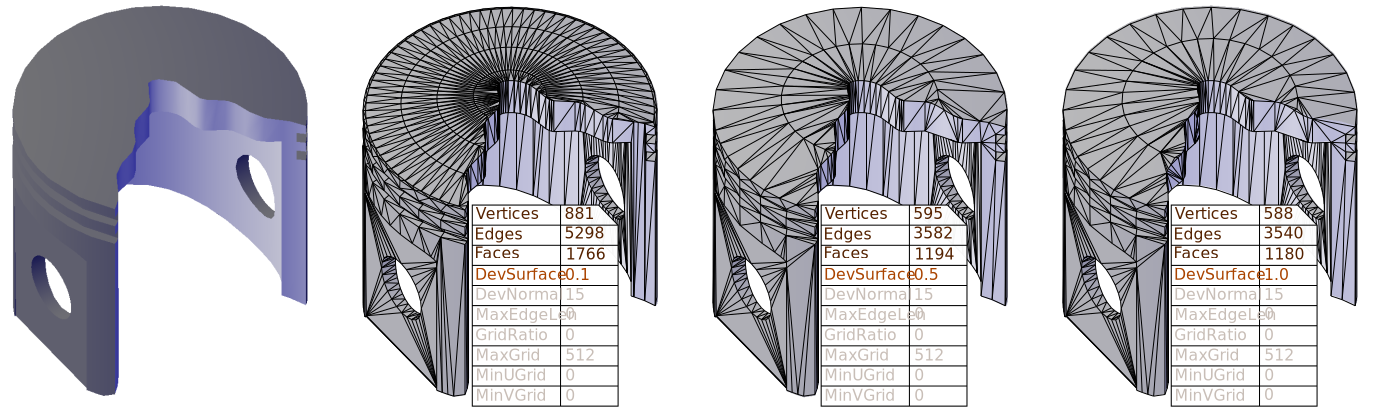
Fig 1. faceterDevSurface in Spatial Modeler.
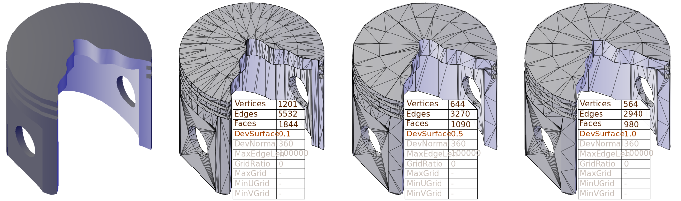
Fig 2. faceterDevSurface in ModelerGeometry.
faceterDevNormal
The faceterDevNormal parameter controls the deviation of angles of the resulting adjacent faces created from one surface.
The closer it is to zero, the more accurate the result is, and the more faces are created.
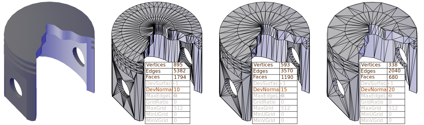
Fig 3. faceterDevNormal in Spatial Modeler.
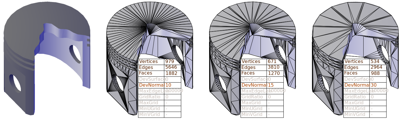
Fig 4. faceterDevNormal in ModelerGeometry.
faceterMaxEdgeLength
The faceterMaxEdgeLength parameter limits the length of the edges created.
The effect of this parameter is very noticeable on planar faces.
The closer it is to zero, the more accurate the result is and the more faces are created.
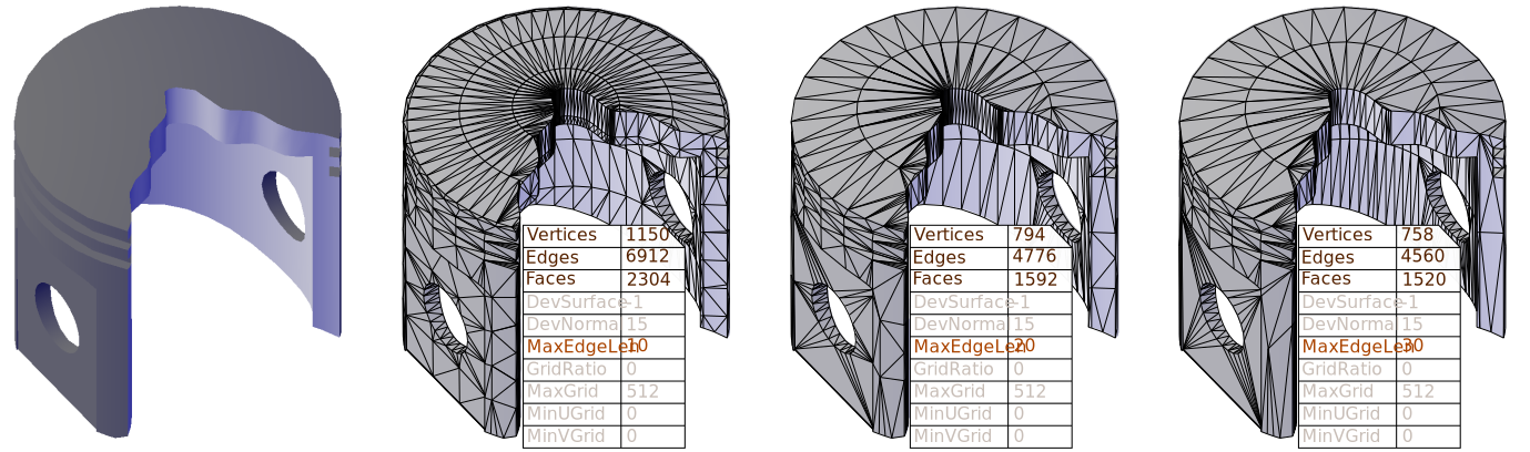
Fig 5. faceterMaxEdgeLength in Spatial Modeler.
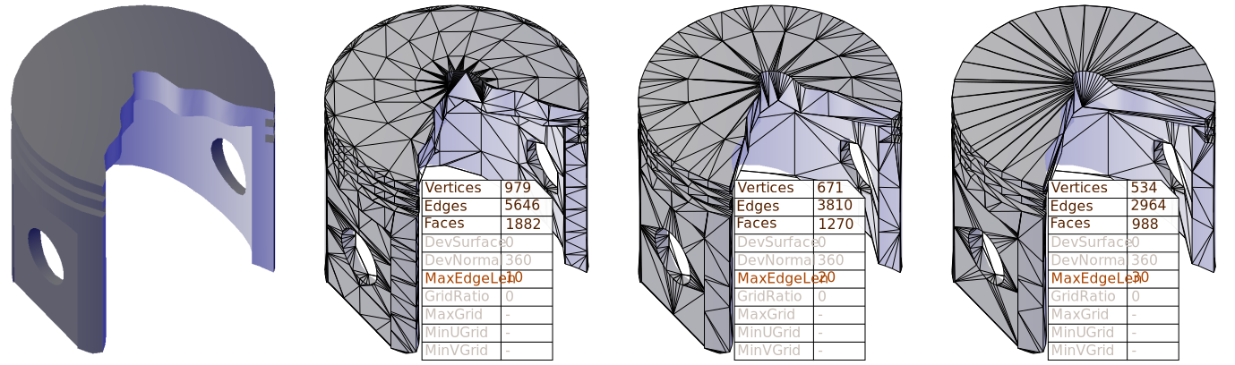
Fig 6. faceterMaxEdgeLength in ModelerGeometry.
The remaining parameters do not affect the result of the method in ModelerGeometry, an example of the results with Spatial Modeler are given below.
faceterGridRatio
The faceterGridRatio parameter determines the maximum aspect ratio of the rectangles in the grid.
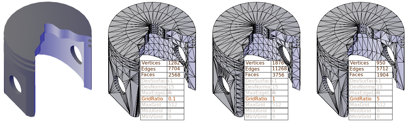
Fig 7. faceterGridRatio in Spatial Modeler.
faceterMaxGrid
The faceterMaxGrid parameter sets the maximum number of lines in the created mesh per surface grid.
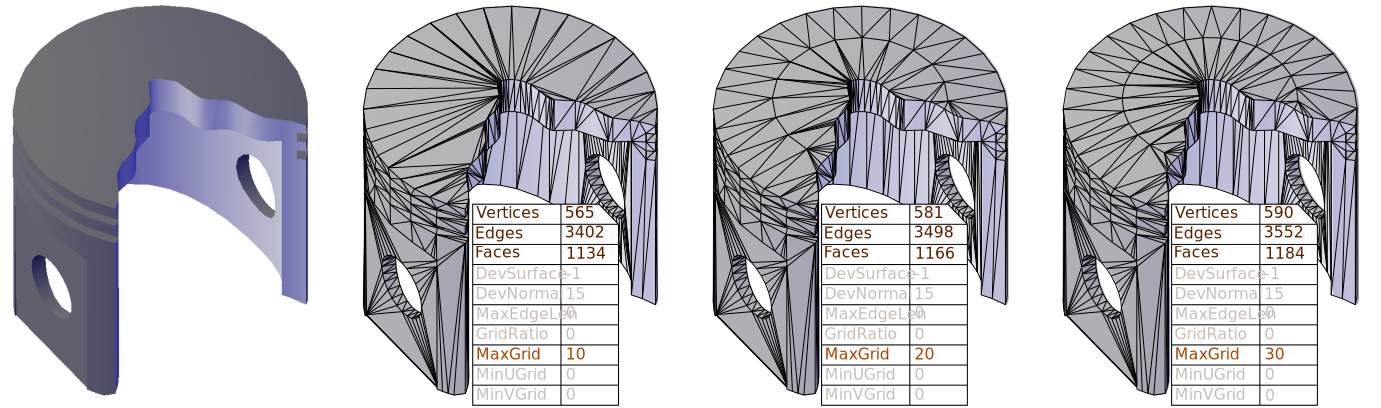
Fig 7. faceterMaxGrid in Spatial Modeler.
faceterMinUGrid
The faceterMinUGrid parameter sets the minimum number of lines in a grid by the U parameter.
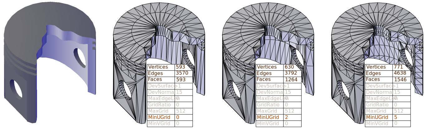
Fig 9. faceterMinUGrid in Spatial Modeler.
faceterMinVGrid
The faceterMinVGrid parameter sets the minimum number of lines in a grid by V parameter.

Fig 10. faceterMinVGrid in Spatial Modeler.
faceterMeshType
The last faceterMeshType parameter is not used, as a mesh of triangles is always created.
Below you can see how to call a command convtomesh.
To read more about the differences between ModelerGeometry and Spatial Modeler, see the Compare Functionality of Available Modelers topic.