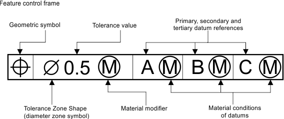
A feature control frame is a group of symbols that contain information about conditions and tolerances of a geometric object, typically a part. Feature control frames contain the following:
- Control symbol — Symbol that specifies the geometric control.
- Tolerance zone type and value — Diameter symbol (if required) and tolerance value in the same measurement as the measurement of the drawing.
- Tolerance zone modifiers — Modifiers of the tolerance zone, for example, maximum size, projections, etc.
- Datum references — Letter that corresponds to a feature that is marked with the same letter on the geometric object.
Example of a feature control frame is shown in the picture below.

For working with feature control frames, use the OdDbFcf class, which represents a feature control frame and allows users to access a feature control frame entity and manipulate its properties. The OdDbFcfPtr class is the typified smart pointer to an instance of this entity, and it is used for storing and passing references to the feature control frame objects.
To create and initialize a new instance of a feature control frame entity, see Overview of Specific Entities.
To attach a feature control frame entity to a leader, see Working with Annotations of Leaders.
See Also
Working with Feature Control Frames