BimRv SDK provides functionality that allows modifying an existing family with geometry elements and importing the modified family into a .rvt project. The topic describes how it can be done for an extrusion element.
Let's assume that we have downloaded a specified .rfa file into a BimRv database instance and are able to refer to this database using a smart-pointer:
OdString fileName = pIO->getFilePath(L"Set file name.rfa", OdEd::kGfpForOpen, L"Select RFA", L"rfa", L"", "RFA files (*.rfa)|*.rfa");
if (!odrxSystemServices()->accessFile(fileName, Oda::kFileRead)) {
  pIO->putString(message.format(L"%ls is not accessible", fileName.c_str()));
  return;
}
OdBmHostAppServices* pServices = pDb->appServices();
pIO->putString(message.format(L"Read file: %ls", fileName.c_str()));
auto pImportingDb = pServices -> readFile(fileName);
Consider how a new geometry (an extrusion element) can be created within the family:
-
Create the array of curve loops that is necessary for the extrusion process
and define the identifier of the sketch plane that contains the extrusion element.
It is also needed to create an intermediate array of curves that makes the curve loop.
OdArray<OdBmCurveLoopPtr> arrCurveElems; OdBmObjectId sketchPlaneId = pImportingDb->getObjectId(OdDbHandle(501)); OdBmGCurvePtrArray arrCurvesOfLoop; -
Create lines (curves) for the loop and add them to the curve array:
{ OdBmGLinePtr pGLine = OdBmGLine::createObject(); pGLine->set(OdGePoint3d(1000, 100, 0), OdGePoint3d(1000, 0, 0)); arrCurvesOfLoop.append(pGLine); } { OdBmGLinePtr pGLine = OdBmGLine::createObject(); pGLine->set(OdGePoint3d(1000, 0, 0), OdGePoint3d(900, 0, 0)); arrCurvesOfLoop.append(pGLine); } { OdBmGLinePtr pGLine = OdBmGLine::createObject(); pGLine->set(OdGePoint3d(900, 0, 0), OdGePoint3d(900, 100, 0)); arrCurvesOfLoop.append(pGLine); } { OdBmGLinePtr pGLine = OdBmGLine::createObject(); pGLine->set(OdGePoint3d(900, 100, 0), OdGePoint3d(1000, 100, 0)); arrCurvesOfLoop.append(pGLine); } -
Create the curve loop instance, add the array of curves (lines) to it and append the created curve loop object to the
curve loops array:
OdBmCurveLoopPtr pCurveLoop = OdBmCurveLoop::createObject(); OdResult res = pCurveLoop->set(arrCurvesOfLoop); arrCurveElems.append(pCurveLoop); -
Create the extrusion element:
OdBmExtrusionElemPtr pExtrusion = OdBmExtrusionElem::createObject(); -
Add extrusion element to the BimRv database associated with the family and proceed with the extrusion according to
necessary parameters and previously created curve loop stored in the curve loops array.
Don't forget to do all operation within a database transaction:
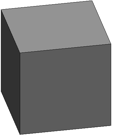
ODBM_TRANSACTION_BEGIN(t, pImportingDb)
  t.start();
  pImportingDb->addElement(pExtrusion);
  pExtrusion->setStartEndExtrursionParam(0, 100);
  pExtrusion->addCurveLoops(arrCurveElems, sketchPlaneId);
  t.commit();
ODBM_TRANSACTION_END()
arrCurveElems.clear();
After the transaction finishes, the array of curves can be cleared.
The picture below shows the created extrusion element:
Now it is possible to import the modified .rfa family into a BimRv (.rvt) project:
// Import .rfa database into .rvt database.
pIO->putString(message.format(L"loadFamily to Model"));
pDb->loadFamily(pImportingDb);
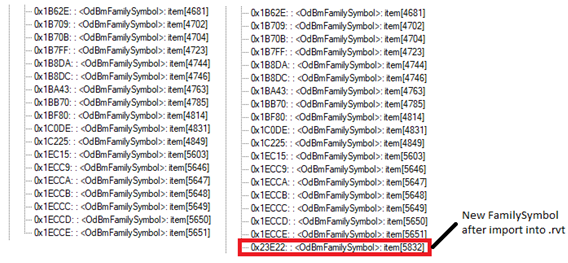
If you run the OdaBimApp example application and load the appropriate .rvt file you can see the new family symbol in the project structure.
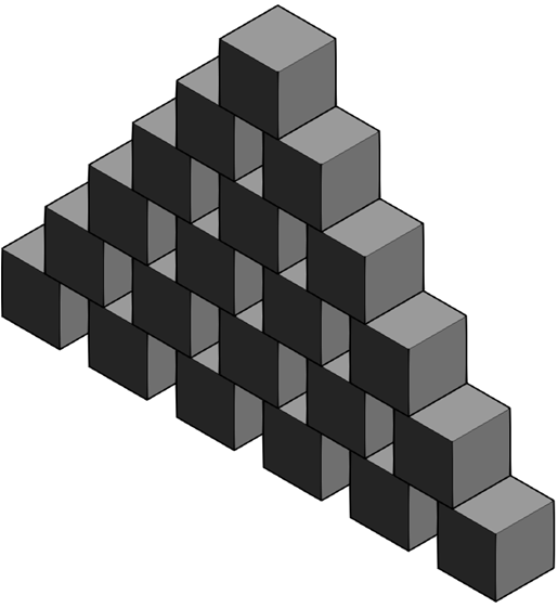
The creation of a set of family instances can be illustrated with a code that adds several extrusion elements with a specified shift along X-axis and Y-axis.
OdGePoint3d location = OdGePoint3d::kOrigin;
for (OdUInt32 iIndex = 0; iIndex <= iHeight; iIndex++) {
  double dShiftX = iIndex * 75.0;
  double dShiftZ = iIndex * 100.0;
  for (OdUInt32 iCube = 0; iCube <= iHeight - iIndex; iCube++) {
    location = OdGePoint3d(dShiftX + (iCube * 150.0), 0, dShiftZ);
    OdString sInput;
    sInput.format(L"%i %f,%f,%f",
                  OdUInt64(famSymId.getHandle()),
                  location.x,
                  location.y,
                  location.z);
    OdSmartPtr<ExStringIO> pStringIO = ExStringIO::create(sInput);
    OdBmCommandContextPtr pDbCmdCtx =
        ExBimCommandContext::createObject(pStringIO, pDb);
    ODBM_THROW_IF_NOT_TF_OK(OdBm::Utils::executeCommand(L"BmNotHostedFamInstCreate",
                                                        pDbCmdCtx));
  }
}
You can see the set of family instances as a result of this operation in the picture:
You can find the full source code in the TB_Commands example
(see the BimRv/Examples/TB_Commands/BmFamilyImportCmd.cpp file).