A dimension entity's graphic representation is stored in file as an anonymous block (Block Table Record) with a name starting with *D. The block contains lines, solids, multiline text, points, and block reference entities.
The dimension entity itself stores a reference to the block. The geometry block that it actually contains depends completely on the application that saved the file. An application can create a block with any geometry for a dimension entity, and this block is displayed after file loading.
If a dimension entity is edited by an application, its block gets recalculated based on points stored in the dimension entity and properties stored in the dimension style (or dimension entity XData overrides). If the block does not match the dimension properties, even changing its color from ByBlock to ByLayer or minimal dragging of a grip point may significantly change the dimension's appearance.
Files with dimension entities that have no dimension blocks theoretically are correct, but some applications (including a couple of Autodesk® AutoCAD® versions such as 2010) will not display dimension entities if they have no blocks in file.
Using dimension block computing functionality
Dimension block computing functionality resides in the RecomputeDimBlock module. In a DLL configuration, this is the .tx module which should be present in the application’s folder. In static configurations, it should be included into a Static Module Map. It is strongly recommended to include this module in an application:
- to not create files that contain dimension entities without blocks.
- to display dimension entities in the case that they have no blocks in the file.
If a dimension entity is created or edited, the RecomputeDimBlock module will create or update its dimension block in the following conditions:
- At the moment the dimension is closed (last smart pointer to it goes out of scope or is assigned another value)
- downgradeOpen() is called for a dimension entity
- recomputeDimBlock() is called explicitly
The same is for updating a dimension's measured value returned by the measurement() method.
By default, if client code has not turned off Drawings dimension block computing functionality explicitly and the RecomputeDimBlock module is absent, an exception is thrown to prevent creating files where dimensions are not displayed.
Turning off Drawings dimension block computing functionality
There are a few ways to turn off automatic dimension block recalculation:
- Turn off dimension blocks calculation completely.
If you are sure it’s OK in your specific case, you can not include the RecomputeDimBlock module in your application. However, you need to set the OdDbHostApp variable “RecomputeDimBlocksRequired” to “false”. Otherwise, an exception will be thrown during the attempt to load or create a new drawing (designed to avoid situations when the module was dropped unintentionally). pHostAppServices->setRecomputeDimBlocksRequired(false);
- Turn off dimension block recomputing for a specific entity.
After all properties (including Dimension Block ID if present) are set for the entity, call pDimension->recordGraphicsModified(false);
- Turn dimension blocks recalculation on and off. If dimension block recalculation is on or off at
application start depends on whether you have called pHostAppServices->setRecomputeDimBlocksRequired(false);
or not.
To disable it:
appServices->setRecomputeDimBlocksRequired(false);
::odrxDynamicLinker()->unloadModule(OdRecomputeDimBlockModuleName);
To turn it on:
appServices->setRecomputeDimBlocksRequired(true);
::odrxDynamicLinker()->loadModule(OdRecomputeDimBlockModuleName);
Dimension breaks
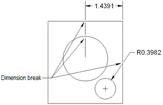
Drawings SDK supports dimension breaks while recomputing dimension blocks. Dimension breaks are supported for the following objects: aligned linear dimensions, rotated linear dimensions, two- and three-point angular dimensions, radial and diameter dimensions, arc-length dimensions, ordinate dimensions, and straight multileaders. Dimension breaks are not supported for the following objects: spline multileaders, straight or spline legacy leaders, or xrefs. When removing breaks from a dimension or leader object, all dimension breaks are removed. This feature applies to those drawings which contain a specified dimension with break data. An object can be broken if its edges are a dimension, leader, line, circle, arc, spline, ellipse, polyline, single-line text, multi-line text, or block.

The OdBreakDimEngine class represents the following methods: addBreakPoint(), breakDimensionLine(), breakAngle(),
collectBreakPoints(), breakBy2StaticPoint(), intersectWithArc(), intersectWithLine(),
intersectWithText(), intersectWithPolyline(),
intersectWith2DPolyline(), intersectWithEllipse(),
intersectWithSpline(), intersectWithLeader(),
intersectWithDimension(), intersectWithBlock(), setDimensionEnts(),
breakDimension(). The TX module contains this class.
Multileader breaks
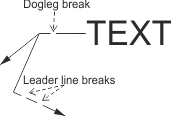
Since Teigha version 4.1, multileaders support partial dimension breaks (input/output and rendering). The break(s) can be set to the specified leader line or to the dogleg.

The leader line break is described by the following structure:
struct BreakInfo
{
    OdInt32 m_nSegment;
    OdGePoint3dArray m_StartPoints;
    OdGePoint3dArray m_EndPoints;
};
- m_nSegment — Specifies the number of vertices after which the breaks are placed. The vertices are numbered starting from the arrow and ending with the "connection point".
- m_StartPoints — An array of three-dimensional points that defines the coordinates of the break(s) start.
- m_EndPoints — An array of three-dimensional points that defines the coordinates of the break(s) end.
The described structure is used by the methods setBreaks() and getBreaks() for setting and getting the break(s) of a specified leader line. The example of using the setBreaks() method is given below. In this example, the pMLeader variable is a smart pointer to an OdDbMLeader object.
    ...
    int  llIndex;
    // add leader
    OdGePoint3d point( 2.5, 1.5, 0.0 );
    pMLeader->addLeaderLine( point, llIndex );
    OdGePoint3d nextPoint = point;
    point.x += 1;
    point.y -=0.5;
    pMLeader->addFirstVertex( llIndex, point );
    OdGeVector3d d = nextPoint - point;
    // create an array of breaks
    OdArray<OdDbMLeaderBreaks::BreakInfo> breaks;
    breaks.resize(1);
    breaks[0].m_nSegment = 0;
    breaks[0].m_StartPoints.append( point + d*0.3 );
    breaks[0].m_StartPoints.append( point + d*0.7 );
    breaks[0].m_EndPoints.append( point + d*0.4 );
    breaks[0].m_EndPoints.append( point + d*0.8 );
    // set breaks to the specified multileader and leader line
    OdDbMLeaderBreaks::setBreaks( pMLeader, llIndex, breaks );
    ...
The code below demonstrates how to use the getBreaks() method. This method returns an array of BreakInfo structures with the break's information specified by an index leader line (llIndex) for the specified multileader (pMLeader).
    ...
    OdArray<OdDbMLeaderBreaks::BreakInfo> mLeaderBreaks;
    OdDbMLeaderBreaks::getBreaks( pMLeader, llIndex, mLeaderBreaks );
    ...
To set breaks on the dogleg, use the setDoglegBreaks() method. The input parameters of this method are: pointer to an OdDbMLeader object, number of the leader cluster, and two arrays of three-dimensional points that define the coordinates of the start and end break(s) points. The example of using this method is given below.
    ...
    // get connection point
    OdGeVector3d direction( 0.0, 1.0, 0.0 );
    OdGePoint3d connectionPoint;
    pMLeader->connectionPoint( direction, connectionPoint );
    // create an array of start points of breaks
    OdGePoint3dArray startPoints;
    startPoints.resize(1);
    startPoints[0] = OdGePoint3d( connectionPoint.x-0.3, connectionPoint.y, connectionPoint.z );
    // create an array of end points of breaks
    OdGePoint3dArray endPoints;
    endPoints.resize(1);
    endPoints[0]= OdGePoint3d( connectionPoint.x-0.2, connectionPoint.y, connectionPoint.z );
    // add dogleg break
    int leaderRootIndex = 0;
    OdDbMLeaderBreaks::setDoglegBreaks( pMLeader, leaderRootIndex, startPoints, endPoints );
    ...
In this example the connection point is a point on the dogleg, which is the most distant from the content (text/block).
To get the information about breaks that are placed on the dogleg, use the getDoglegBreaks() method. This method has two input parameters (smart pointer to an OdDbMLeader object, number of leader cluster) and two output parameters (arrays of three-dimensional points that define the coordinates of start and end breakspoints). The example of using this method is given below.
    ...
    int leaderRootIndex = 0;
    OdGePoint3dArray newStartPoints, newEndPoints;
    OdDbMLeaderBreaks::getDoglegBreaks( pMLeader, leaderRootIndex, newStartPoints, newEndPoints );
    ...
See Also
Copyright © 2002 – 2020. Open Design Alliance. All rights reserved.
|